


 English
 中文简体
 русский
Industry news
 Home / News / Industry news / Siphonic Roof Drainage Explained: How It Works, Where It Fits, and What to Check
Siphonic Roof Drainage Explained: How It Works, Where It Fits, and What to Check
 2026.11.20
 Industry news
Start with the roof drain, not the pipe
The roof drain sets the hydraulic limit of a siphonic system; the pipe only follows it. On a large flat roof, a small change at the outlet—grate open area, sump depth, air separation, or outlet spacing—can change the whole pipe layout, the number of vertical stacks, and the structural openings. That is why a siphonic roof drainage review should begin at the drain, not at the pipe schedule.
Picture a 20,000 m² distribution center with a low-slope roof, long internal valleys, and a tight ceiling void. A gravity system may need many large outlets and deep horizontal runs. A siphonic system can often use fewer outlets and smaller-diameter pipes, but only if the roof drains are selected and positioned to support full-bore flow. The same roof area can produce very different results depending on rainfall intensity, roof slope, outlet spacing, and the amount of air that enters the system.
 Siphon Roof Drain for Siphonic Roof Drainage SystemsRoof drain designed to support full-bore siphonic flow, with anti-clogging drainage and compact installation for low-slope roof projects.View Product →
Hydraulic conclusion
Siphonic drainage is a designed hydraulic system, not a parts list. The drain, pipe, fittings, brackets, and discharge must be checked together.
Commercial effect
Fewer outlets and smaller pipes can reduce roof penetrations and ceiling conflicts, but only when the design has enough hydraulic margin for the local storm profile.
Installation effect
A drain that is set too high, too low, or poorly sealed can defeat a well-sized pipe network before the first storm.
How siphonic roof drainage works in practice
A siphonic roof drainage system uses the same physical principle as a siphon: once the pipe is full of water and the outlet is lower than the roof inlet, the weight of the falling water column creates a pressure difference that pulls water into the system. The roof drain is designed to suppress air entry and create a stable vortex. The pipework is designed to fill quickly, run full, and discharge with high velocity.
In the first minutes of rain, the system behaves like a conventional drain. Water flows along the pipe invert, air remains above it, and flow is open-channel. As the rainfall rate rises, the water level in the pipe increases. The outlet and pipe layout are arranged so that a water seal forms at the bottom of the vertical stack. Once that seal is stable, air is pushed out, the pipe fills, and the system enters full-bore flow. The pressure inside the horizontal pipe drops below atmospheric pressure, and the roof outlets draw water in more efficiently.
The transition is the critical part. If the pipe cannot fill fast enough, if air is pulled in through the roof drain, or if the vertical stack is too short, the system may stay in a mixed air-water state. That state can be noisy, inefficient, and unstable. A good siphonic design does not simply make the pipe smaller. It controls fill time, pressure distribution, velocity, and air separation.
| Design point | Conventional gravity roof drainage | Siphonic roof drainage |
|---|---|---|
| Flow condition | Open-channel flow with air above the water surface. | Full-bore flow after the pipe fills and the siphon forms. |
| Pipe slope | Relies on a continuous fall. | Can run with less fall, but pressure and air control become more important. |
| Outlet count | Often higher because each outlet works at low capacity. | Often lower because outlets work together under negative pressure. |
| Main risk | Standing water from insufficient slope or blocked outlets. | Poor fill, air entrainment, excessive negative pressure, or blocked air paths. |
The anatomy of a siphonic roof drainage system
A siphonic roof drainage system is compact at the roof but more demanding below it. Each component has a hydraulic or structural role. The roof drain is not just a grate; it is an air-control device. The hopper or sump helps stabilize flow. The horizontal pipe carries the system toward the stack. The vertical stack provides the water column that creates the siphon. The discharge line must release the water without back-pressure that destabilizes the system.
 HDPE Siphon Drainage Hopper for Roof Drainage SystemsHDPE hopper for siphonic roof drainage, designed to stabilize flow and reduce drainage noise while offering corrosion-resistant, modular installation.View Product →
Roof drain and sump
Controls vortex formation, excludes large debris, and connects the roof membrane to the pipe. Grate open area and sump depth matter as much as the outlet diameter.
Horizontal pipework
Carries full-bore flow with controlled pressure loss. Changes in direction, reducers, and branch fittings must be selected to avoid air pockets and excessive turbulence.
Vertical stack
Creates the falling water column. The stack base and transition to horizontal discharge need careful support and pressure control.
Fittings and joints
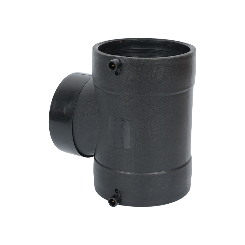
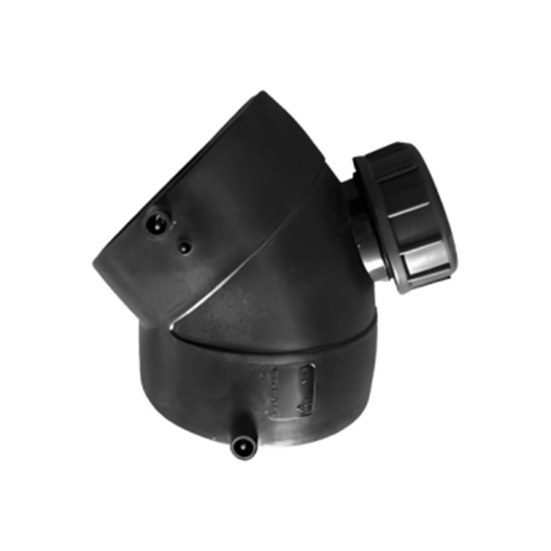
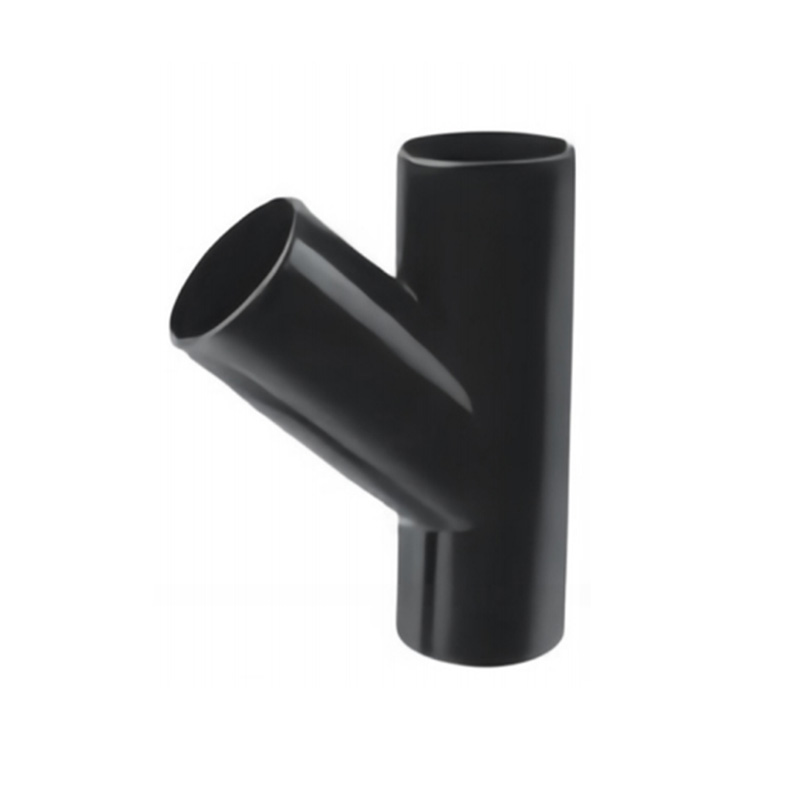
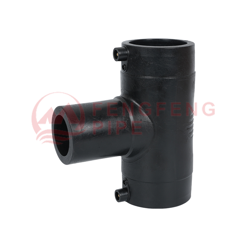
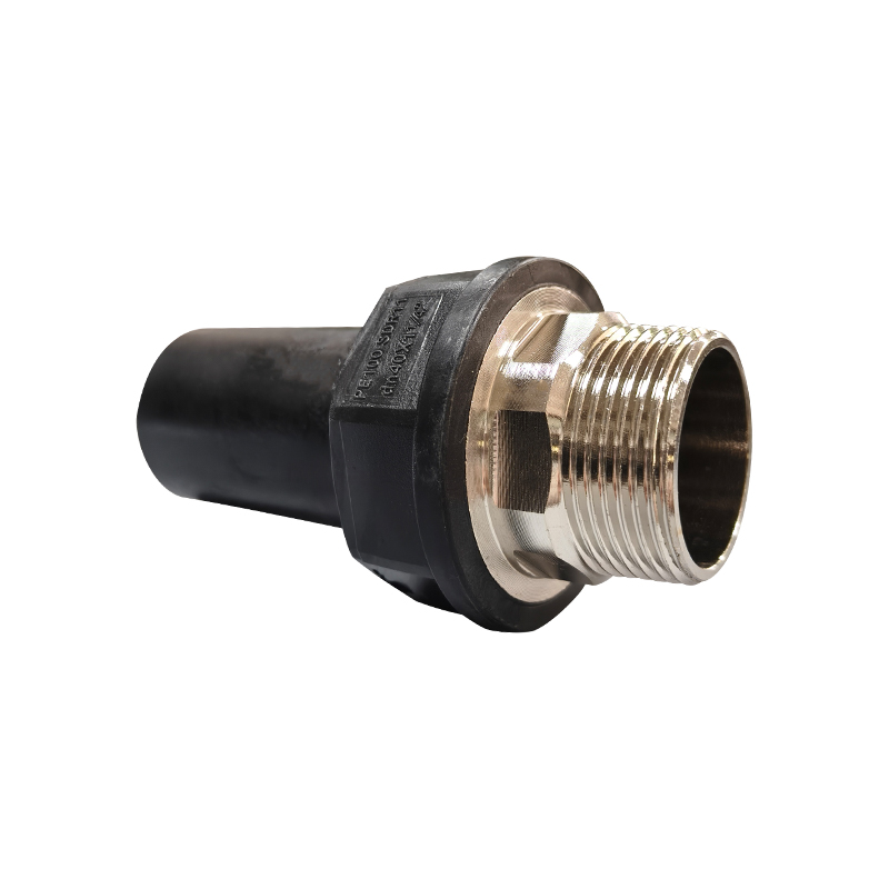
HDPE elbows, tees, couplers, reducers, cleanouts, and transition pieces keep the system tight and hydraulically smooth.
Brackets and anchors
Hold the pipe against negative pressure, thermal movement, and water hammer. Spacing is not a cosmetic detail; it protects joint integrity.
Discharge and cleanout
Allows unobstructed release to the stormwater network and gives maintenance access without dismantling the pipe run.
Material choice follows the same logic. HDPE is common for siphonic drainage because it is smooth, corrosion-resistant, lightweight, and available in fusion-jointed fittings. Fusion joints reduce the number of mechanical seals inside the pipe, which matters when the system operates under negative pressure. The pipe must also handle UV exposure at the roof, thermal movement in long runs, and the structural loads imposed by wind and maintenance traffic.
Where siphonic roof drainage is used and where it is not
Siphonic roof drainage is most useful where the roof is large, the roof slope is low, and the building has limited space for many gravity pipes. It is common on warehouses, factories, logistics centers, shopping centers, airport terminals, exhibition halls, stadiums, car parks, data centers, and large canopies. The system also suits buildings with long roof spans where internal columns are limited and outlets need to be concentrated into fewer vertical stacks.
The system is not automatically the right answer for every roof. A small roof with simple geometry, easy gravity falls, and low rainfall intensity may be better served by conventional drainage. A roof with many level changes, many small catchment areas, or frequent obstructions may not fill reliably. A project with limited maintenance access should also pause: a siphonic system depends on clear outlets and stable air control, so blocked drains can reduce performance quickly.
Good fit
Large flat roofs, long pipe runs, tight ceiling voids, few vertical stack locations, and a storm profile that can be modeled with local code data.
Needs caution
Roofs with many isolated pockets, short vertical stacks, complex discharge conditions, or a high risk of debris accumulation.
Poor fit
Very small roofs, roofs where standing water is acceptable, or projects where maintenance access to outlets and cleanouts is not realistic.
For industrial buildings, the decision often comes down to outlet count and pipe routing. Fewer roof penetrations can reduce leak risk and structural work. Smaller pipes can fit above ceilings or inside service zones. But those gains depend on a correct hydraulic model, not on a catalogue rule of thumb. A system that is undersized for a local cloudburst may still overflow even if it performs well in a light rain test.
Design checkpoints that decide whether the system works
The design must start with local rainfall data and the actual roof catchment. Rainfall intensity is usually selected from local code or project-specific storm data. The design should state the return period, the storm duration, and whether climate allowance has been added. A siphonic system can be sensitive to short, intense storms because the pipe must fill quickly enough to form the siphon.
Roof area is not the only input. The catchment shape, slope, outlets, parapets, expansion joints, and adjacent higher roofs all affect flow. The designer should check whether water can bypass an outlet, whether ponding can occur between outlets, and whether the roof structure can carry temporary water loads during a blockage or extreme event.
| Checkpoint | What to verify | Why it matters |
|---|---|---|
| Rainfall input | Local intensity, return period, duration, and climate allowance. | Sets the design flow and the fill condition. |
| Roof catchment | Area, slope, ponding zones, parapets, and outlet spacing. | Prevents bypass flow and local standing water. |
| Pipe fill | Fill time, air removal, and stable siphon formation. | Controls whether the system reaches full-bore flow. |
| Pressure profile | Negative pressure limits, velocity, and stack base pressure. | Protects joints, reduces noise, and avoids unstable flow. |
| Structural interface | Roof openings, sleeves, anchors, and thermal movement. | Reduces leak paths and pipe stress. |
| Discharge | Outlet submergence, back-pressure, and storm network capacity. | Allows the siphon to release water without surging. |
A common review mistake is to compare only pipe diameters. Two layouts with the same diameter can perform differently because of fitting pressure loss, air pockets, stack height, or discharge conditions. A useful review compares the hydraulic model, the roof drain schedule, the support drawing, and the commissioning plan together. If one of those documents is missing, the system is not fully defined.
Installation, jointing, and commissioning
HDPE siphonic pipework is usually joined by butt fusion, electrofusion, or socket fusion, depending on diameter, site access, and project specification. Fusion joints are strong and smooth inside the pipe, but they depend on correct surface preparation, heating time, alignment, and cooling. A joint that looks acceptable from the outside can still have a weak interface if the pipe ends were contaminated or the fusion cycle was rushed.
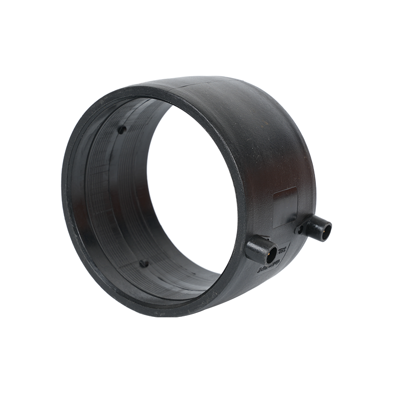 HDPE Electrofusion Coupler for Siphonic Pipework ConnectionsElectrofusion coupler for joining HDPE siphonic pipework, offering leak-free connections and chemical resistance across multiple diameters.View Product →
Brackets and anchors need more attention than in a gravity system. Under negative pressure, the pipe is pulled inward and can move. Long horizontal runs expand and contract with temperature. Vertical stacks need guides that allow movement without transferring load to the roof drain. Roof penetrations must be sealed to the waterproofing system, and the drain flange must sit at the correct level so water does not pond around the outlet.
Commissioning should include a flush, a visual check of every outlet, a joint inspection, and a watertightness or airtightness test according to the project specification. The test should not be treated as a final formality. It is the point where installation errors become visible: a missed fusion cycle, a loose bracket, a damaged gasket, or a cleanout left partially open. For projects in variable climates, the installation plan should also account for temperature and UV exposure; the same HDPE system may need different handling in cold or hot conditions, as discussed in this guide to HDPE siphon drainage climate adaptation.
Before jointing
Check pipe roundness, cut square, clean surfaces, mark insertion depth, and confirm the fusion machine calibration.
During installation
Keep debris out of open pipe ends, protect gaskets, and do not force misaligned joints into position.
At handover
Record test results, outlet positions, bracket spacing, cleanout access, and any site modifications to the design.
Maintenance, inspection, and common failure points
Siphonic roof drainage does not need daily attention, but it does need planned inspection. The highest-risk points are the roof drains, leaf guards, cleanouts, and any low point where debris can collect. A blocked outlet may not cause immediate flooding if other outlets are working, but it can change the pressure balance and reduce system capacity. After a major storm, a quick roof-level check is more useful than waiting for a ceiling stain to appear.
Blocked roof drain
Leaves, packaging, and roof gravel can cover the grate. Check outlet clearances before and after seasonal debris periods.
Air entry
A damaged gasket, open cleanout, or poorly sealed transition can break the siphon. Look for noise, surging, or uneven flow.
Pipe movement
Loose brackets, missing anchors, or thermal movement can stress joints. Inspect supports after extreme temperature cycles.
Discharge restriction
A surcharged storm network or blocked discharge can back up into the stack. Confirm the outlet condition during heavy rain.
Maintenance access should be designed, not improvised. Cleanouts need to be reachable without removing ceiling panels or cutting pipe. Roof drains need safe access from a walkway or service route. If the building owner cannot inspect the system safely, the design is incomplete regardless of hydraulic performance.
Fitting selection and procurement questions
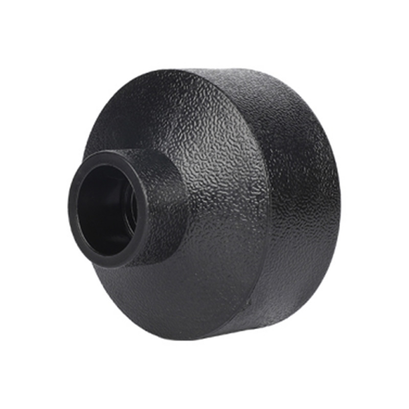
Fitting selection should follow the hydraulic design and the installation method. A siphonic system may use large-diameter HDPE elbows, equal and reducing tees, eccentric reducers, couplers, cleanouts, drain hoppers, and transition pieces. Each fitting has a pressure loss and an installation orientation. A reducer installed in the wrong plane can trap air; an elbow with a tight radius can add turbulence; a bracket placed too far from a joint can concentrate stress.
Useful procurement questions include: Does the fitting match the pipe material and SDR? Is the fusion method compatible with site equipment? Are the pressure ratings and wall thicknesses documented? Are gaskets and seals suitable for the expected temperature range? Is there a traceability system for production batches? Are drawings, test reports, and installation instructions available? These questions are more valuable than a generic price comparison because they reveal whether the package can be installed and maintained as designed.
HDPE Siphon Drainage Hopper for Roof Drainage SystemsHDPE hopper for siphonic roof drainage, designed to stabilize flow and reduce drainage noise while offering corrosion-resistant, modular installation.View Product →
Material consistency
Pipe, fittings, and fusion parameters should come from a controlled system, not a mixed set of unknown origin.
Hydraulic shape
Fitting geometry affects pressure loss and air movement. Ask for dimensional data when the layout is tight.
Project support
Drawings, bills of material, and installation guidance reduce site errors and help the contractor plan the work.
For buyers comparing manufacturers, the useful question is not only who can supply a box of fittings. It is who can support the hydraulic intent with consistent product data, reliable fusion performance, and practical installation details. A manufacturer with experience across HDPE pipe, fusion fittings, and drainage components can often spot interface problems earlier. More background on production and quality management is available on the company profile page.
Frequently asked questions
Does a siphonic roof drainage system need a minimum roof slope?
It still needs a roof that directs water to the outlets. The slope can be lower than a conventional gravity layout in some designs, but standing water, ponding, and local high points must be avoided. The roof drain should sit at the low point of its catchment, and the waterproofing must not create a lip around the outlet.
Can siphonic drainage handle the same storm as gravity drainage?
It can be designed for the required storm, but the design basis must be explicit. The system should be checked for the selected rainfall intensity, return period, and duration. It should also have an overflow or secondary safety concept for events beyond the design storm. The fact that a pipe is smaller does not mean the safety margin is smaller; it means the hydraulic analysis must be more precise.
Why does the system sometimes run loudly or surge?
Noise and surging often point to unstable air-water flow. Possible causes include insufficient fill, air entering through a drain or joint, a shallow stack, a discharge restriction, or a layout with trapped air. The fix is not simply to open a valve; the air path and pressure profile need to be reviewed.
Is HDPE suitable for siphonic roof drainage?
HDPE is widely used because it is smooth, corrosion-resistant, lightweight, and suitable for fusion jointing. It can handle the negative pressure of a siphonic system when the pipe, fittings, and supports are correctly specified. UV exposure, fire requirements, and structural loading should still be checked for the specific project.
How often should roof drains be cleaned?
It depends on the roof environment. A building near trees, fields, or industrial dust may need more frequent checks than a clean urban roof. At minimum, inspect before the storm season and after major debris events. Keep a record of outlet condition, cleanout access, and any repairs.
Can a siphonic system be retrofitted to an existing building?
Sometimes, but the roof structure, ceiling void, discharge points, and existing waterproofing all need review. A retrofit may be limited by stack locations, pipe routes, and the ability to create enough vertical fall for siphon formation. A hydraulic survey should come before any fitting selection.
What should be included in a siphonic drainage submittal?
A useful submittal includes the hydraulic calculation, roof plan with catchment areas, outlet schedule, pipe layout, fitting list, support drawing, fusion method statement, testing plan, and maintenance access plan. If any of these documents is missing, the package is difficult to review and easy to install incorrectly.
Does every roof outlet need a separate cleanout?
Not necessarily. The design should provide access at changes of direction, long horizontal runs, and points where debris can collect. Roof-level access is also important. The goal is to allow inspection and clearing without dismantling the system or opening a ceiling.
KEEP IN TOUCH

About Us
Zhejiang Fengfeng Pipe Industry Co., Ltd. uses efficient single screw injection molding machines for high productivity and low energy use.
Products link
Contact
-

+86-19858193396
+86-13735359894 -

+86-0574-63555288
-

-

No. 21, Market Road, Diankou Town, Zhuji City, Shaoxing City, Zhejiang Province, China