Industry news

Zhejiang Fengfeng Pipe Industry Co., Ltd. Home / News / Industry news / How Do HDPE Electrofusion Fittings Ensure Reliable Pipe Connections

How Do HDPE Electrofusion Fittings Ensure Reliable Pipe Connections

Zhejiang Fengfeng Pipe Industry Co., Ltd. 2026.07.06
Zhejiang Fengfeng Pipe Industry Co., Ltd. Industry news

HDPE PIPE CONNECTION GUIDE

How Do HDPE Electrofusion Fittings Create Reliable Pipe Connections?

HDPE electrofusion fittings provide a controlled method for joining polyethylene pipes in water supply, gas distribution, industrial processing, mining, irrigation, drainage, and underground utility systems. The connection is produced by electrically heating resistance wires embedded inside the fitting, creating a homogeneous fusion zone between the pipe surface and the fitting socket.

hdpe electrofusion fittings electrofusion fittings hdpe hdpe pipe electrofusion fittings electrofusion hdpe fittings

Connection Priorities

Material Compatibility Pipe and fitting materials must support consistent molecular fusion.
Controlled Heating Fusion voltage and time must match the fitting identification data.
Stable Cooling The joint must remain fixed until the specified cooling period is complete.

WORKING PRINCIPLE

What Happens Inside an Electrofusion Joint?

An electrofusion fitting contains precisely positioned electrical resistance wires within its internal fusion surface. When an electrofusion control unit supplies the required electrical energy, the wires generate heat across the designated welding zones. The inner surface of the fitting and the prepared outer surface of the HDPE pipe gradually soften and melt.

Thermal expansion produces controlled pressure inside the joint. The molten polyethylene layers interpenetrate at the molecular level, forming a continuous fusion interface. After the electrical cycle ends, the connection must remain motionless while the material cools and recrystallizes.

Correctly installed HDPE electrofusion fittings form permanent joints without mechanical threads, sealing rings, bolts, or external adhesives. Joint performance depends on pipe preparation, fitting condition, energy input, alignment, environmental temperature, and cooling control.

Fusion Cycle

01
Surface Preparation

Remove the oxidized pipe layer and all visible contamination.

02
Pipe Positioning

Insert the pipe to the marked depth and secure the assembly.

03
Electrical Heating

Apply the specified voltage and fusion time through the terminals.

04
Joint Cooling

Maintain alignment until the fitting reaches sufficient strength.

PRODUCT CONFIGURATIONS

Common Types of Electrofusion Fittings HDPE Pipe Systems Require

Electrofusion fittings HDPE pipe networks use should be selected according to pipeline direction, branch layout, outside diameter, pressure class, service medium, and available installation space.

01

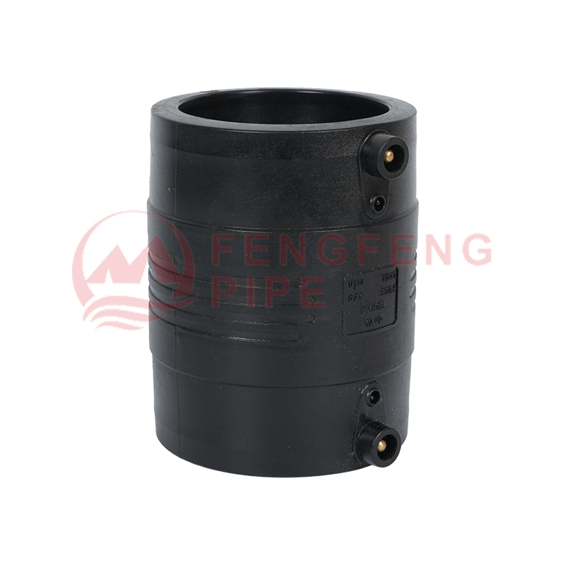
Electrofusion Couplers

Used to connect two straight HDPE pipe sections. Internal heating zones are arranged to produce balanced fusion at both pipe ends while cold zones help control molten material movement.

Typical use: pipeline extension, repair, and replacement

02

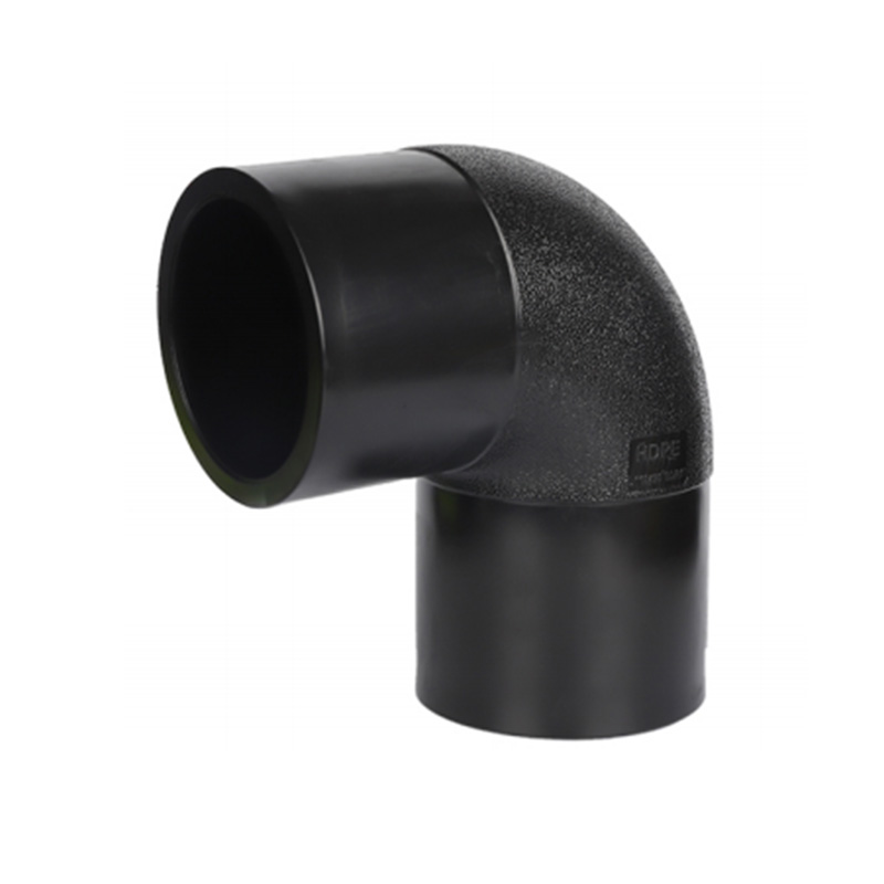
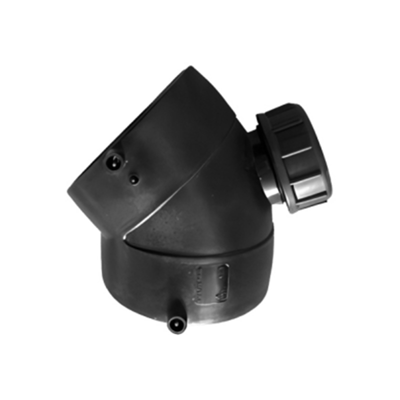
Electrofusion Elbows

Available for directional changes where bending the pipe is unsuitable. Alignment is important because excessive side loading may place long-term stress on the fused sockets.

Typical use: 45-degree and 90-degree pipeline routing

03

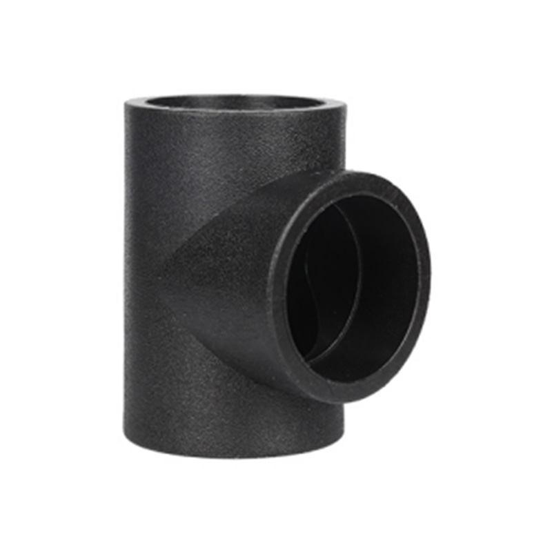
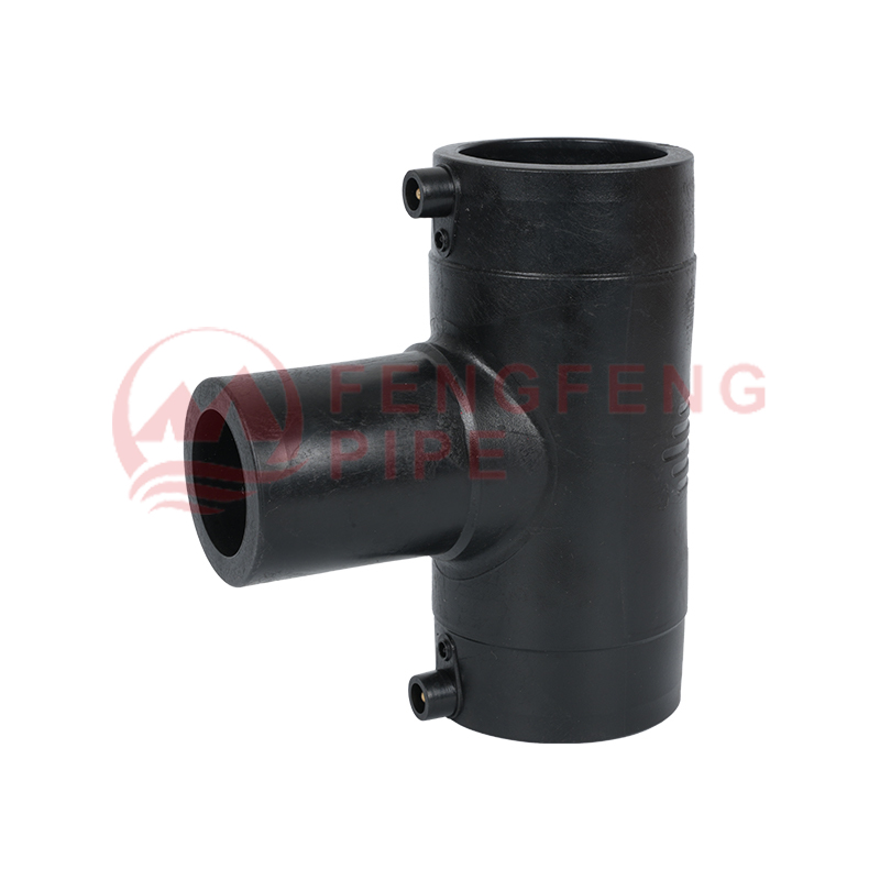
Electrofusion Tees

Designed for equal or reduced branch connections. Flow distribution, branch orientation, pressure loss, and installation clearance should be considered before selection.

Typical use: branch lines and distribution networks

04

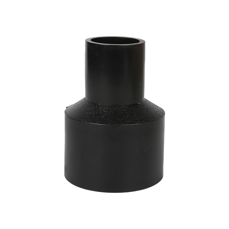
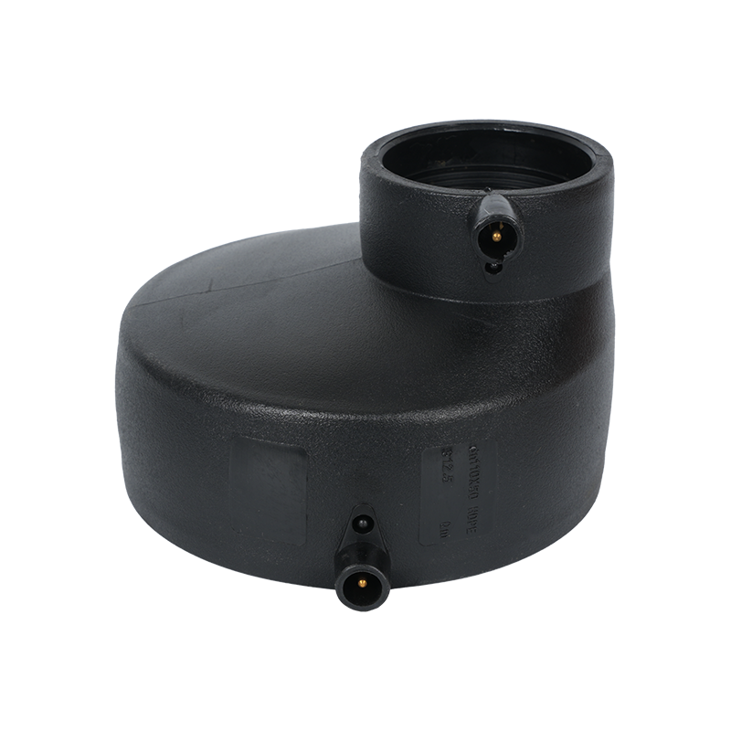
Electrofusion Reducers

Connect HDPE pipes with different outside diameters. The reduction ratio should match hydraulic design requirements to control local turbulence and pressure variation.

Typical use: pipe size transitions

05

Electrofusion End Caps

Seal pipe ends for permanent closure, pressure testing, temporary isolation, or future network expansion. The cap must remain protected from impact during cooling.

Typical use: terminal sealing and test preparation

06

Electrofusion Saddles

Installed over the external surface of a main pipe to create branch or tapping points. Uniform surface contact and secure clamping are critical for a complete saddle fusion area.

Typical use: service branches and live-network additions

SELECTION PARAMETERS

Key Specifications for HDPE Pipe Electrofusion Fittings

HDPE pipe electrofusion fittings must not be selected only by whether the pipe can physically enter the socket. Dimensional compatibility, pressure performance, material classification, fusion data, and operating conditions all influence joint reliability.

Selection Item What to Verify Why It Matters
Outside Diameter Confirm the pipe outside diameter matches the fitting designation. An incorrect diameter can create excessive clearance or prevent full insertion.
SDR Classification Check pipe wall thickness and fitting suitability for the specified SDR. Wall thickness affects pressure capacity, heating behavior, and mechanical strength.
Pressure Rating Select a fitting rating equal to or higher than the pipeline design pressure. Underrated fittings may reduce the safe pressure capability of the complete system.
Material Compatibility Verify that the pipe and fitting polyethylene grades are suitable for fusion. Compatible materials support stable melting, interdiffusion, and cooling behavior.
Fusion Voltage Use the voltage stated on the fitting label, barcode, or technical record. Incorrect voltage may cause insufficient melting or excessive thermal damage.
Fusion Time Follow the specified cycle rather than applying one time setting to every size. Each fitting diameter and heating-wire layout requires a controlled energy input.
Cooling Time Keep the pipe restrained for the complete cooling period. Early movement may disturb the molten interface before sufficient joint strength develops.
Service Medium Consider water, gas, slurry, wastewater, chemical solution, or compressed-air conditions. Medium type, temperature, and operating pressure affect product selection.

INSTALLATION CONTROL

Critical Preparation Steps Before Electrofusion Welding

Most electrofusion failures are associated with preparation, positioning, contamination, or movement rather than the basic heating principle.

01

Cut the Pipe Squarely

The pipe end should be cut perpendicular to the pipeline axis. An angled cut can produce uneven insertion depth and reduce the effective fusion area.

02

Mark the Insertion Depth

Measure the socket depth and place a clear reference mark on the pipe. The mark provides a visible check after the pipe enters the fitting.

03

Remove the Oxidized Layer

Scrape the complete fusion area uniformly with an appropriate rotary or manual scraping tool. Cleaning alone does not replace physical oxide removal.

04

Prevent Recontamination

Do not touch the prepared surface with bare hands. Keep grease, soil, water, dust, and cleaning residue away from the fusion zone.

05

Correct Pipe Ovality

Excessive ovality can create an uneven gap between the pipe and fitting. Rounding equipment may be required before assembly.

06

Secure the Complete Assembly

Use alignment and restraint equipment to prevent rotation, axial movement, bending, or pipe-weight loading during fusion and cooling.

INSTALLATION SEQUENCE

Recommended Procedure for Electrofusion HDPE Fittings

1

Verify the Pipe and Fitting

Confirm diameter, SDR, pressure class, fitting type, terminal condition, traceability information, and intended application.

2

Inspect the Pipe End

Remove sections with cracks, deep scratches, severe deformation, crushing, or contamination that cannot be properly corrected.

3

Cut, Measure, and Scrape

Produce a square cut, mark the socket depth, and remove the complete oxidized surface layer within the insertion zone.

4

Insert and Align

Insert the pipe to the marked position without twisting the fitting excessively. Install alignment clamps before connecting the control unit.

5

Apply the Fusion Cycle

Connect the terminals, scan or enter the required parameters, verify stable power supply, and start the programmed welding cycle.

6

Complete the Cooling Period

Do not remove the clamps, rotate the pipe, backfill the joint, or apply test pressure until the specified cooling time has elapsed.

APPLICATION CONDITIONS

Where Electrofusion Connections Provide Practical Advantages

Restricted Installation Space

Electrofusion does not require the same axial movement as some butt-fusion operations. It is useful in narrow trenches, plant rooms, utility chambers, crossings, and repair locations.

Complex Branch Arrangements

Tees, reducers, saddles, elbows, and transition fittings support compact changes in direction and branch configuration without large mechanical assemblies.

Underground Pipeline Networks

A fused polyethylene connection contains no exposed bolts or seals that require periodic tightening. Correctly installed joints can accommodate normal ground movement with the surrounding HDPE system.

Pipeline Repair Work

Electrofusion couplers can connect replacement pipe sections where moving the existing pipeline is difficult. Repair planning must still provide sufficient space for scraping, clamping, and terminal access.

SITE CONDITIONS

How Temperature, Moisture, and Power Supply Affect Fusion Quality

Low ambient temperatures increase heat loss from the fitting and pipe. High temperatures increase the initial material temperature and may change the amount of energy required to reach the correct fusion condition. The allowable installation temperature range and any automatic compensation function should be verified before welding.

Rain, condensation, mud, and airborne dust can contaminate the prepared pipe surface. Temporary protection should be used during outdoor installation. Water must not enter the fitting socket or remain on the scraped fusion zone.

Unstable generators, long undersized extension cables, and shared high-load equipment can produce voltage fluctuations. The power source should support the required current throughout the complete electrofusion cycle.

Pre-Welding Site Check

Weather Protection The fusion area is dry and shielded from rain, wind, and direct contamination.
Power Stability The power source and cables meet the electrofusion unit requirements.
Pipe Restraint The connected components are free from bending, pulling, and unsupported weight.
Parameter Verification The displayed fusion information matches the fitting identification data.

FAULT IDENTIFICATION

Common Electrofusion Problems and Their Likely Causes

Pipe Cannot Enter the Socket

Possible causes include excessive pipe ovality, burrs, an uneven cut, incorrect diameter, or pipe-end deformation. Forcing the fitting into position can damage the heating wires.

Control Unit Reports Resistance Error

Check terminal contact, lead condition, fitting resistance, parameter recognition, and control-unit compatibility. An alarm should not be bypassed by manually changing the cycle without technical confirmation.

Excessive Melt Appears Outside the Fitting

Possible causes include incorrect fusion data, repeated heating, excessive assembly clearance, over-insertion, or damaged heating-wire placement.

The Joint Moves During Cooling

Pipe weight, inadequate clamping, trench movement, or premature handling can disturb the molten interface and create incomplete bonding.

Fusion Indicator Movement Is Uneven

Uneven indicator response may be associated with poor pipe preparation, irregular socket clearance, incomplete insertion, or inconsistent heating. Indicators are visual references rather than the only acceptance criterion.

Visible Burning or Wire Exposure

Localized burning, severe distortion, or exposed resistance wire indicates abnormal heating or structural damage. The affected joint should not be accepted for service.

QUALITY VERIFICATION

What Should Be Checked After the Fusion Cycle?

Visual Inspection

Check that the fitting retains its intended shape, the pipe insertion marks remain correctly positioned, and no severe melt extrusion, scorching, wire exposure, cracking, or joint displacement is visible.

Installation Records

Record the fitting size, batch information, fusion parameters, equipment identification, operator, location, date, ambient conditions, and any control-unit result code.

Pressure Testing

Begin testing only after all relevant cooling and conditioning requirements are satisfied. Test pressure, hold time, and pressure increase rate should follow the pipeline design and applicable installation procedure.

PROJECT QUESTIONS

Frequently Asked Questions About Electrofusion HDPE Fittings

Can every HDPE pipe be connected with electrofusion fittings?

The pipe diameter, wall thickness, polyethylene material, surface condition, operating pressure, and fitting application range must be compatible. Physical insertion alone does not confirm fusion suitability.

Why must the HDPE pipe surface be scraped before welding?

The external pipe surface develops an oxidized layer during storage and exposure. This layer can prevent effective molecular fusion even when the surface appears visually clean.

Can the same fusion time be used for different fitting sizes?

No. Different electrofusion hdpe fittings may have different resistance values, wire layouts, socket depths, heating zones, and energy requirements. Use the data assigned to the specific fitting.

Can a failed electrofusion joint be welded a second time?

Reheating may cause material degradation, wire displacement, excessive melt pressure, and unpredictable joint performance. A visibly defective or alarmed connection normally requires removal and replacement under the applicable procedure.

When can the alignment clamps be removed?

Clamps should remain installed for the complete cooling time specified for the fitting and site conditions. Removing them immediately after the electrical cycle can disturb the fusion interface.

What information is needed when specifying HDPE electrofusion fittings?

Useful project information includes fitting type, outside diameter, SDR, pressure rating, pipeline medium, operating temperature, required connection arrangement, installation environment, and applicable technical requirements.

PRODUCT CONFIGURATION SUPPORT

Specify the Right Electrofusion Fitting for the Pipe System

Provide pipe diameter, SDR, pressure class, fitting configuration, service medium, operating temperature, and installation conditions to support accurate product matching and technical evaluation.

View Electrofusion Fitting Series

KEEP IN TOUCH

SUBMIT