


 English
 中文简体
中文简体 русский
Industry news

What Are HDPE Pipe Fittings and How Do You Install Them
 2026.07.20
 Industry news
High-Density Polyethylene pipeline systems have redefined modern infrastructure standards across municipal, industrial, and agricultural networks. As a specialized manufacturer, we engineer hdpe fittings and complete pipeline assemblies that meet the rigorous demands of pressurized fluid conveyance and gravity-flow applications. Understanding the full technical profile of hdpe pipe fittings enables project engineers and site contractors to specify the correct grade, dimension, and joining methodology for installations that must remain maintenance-free for decades. From the molecular density of PE100 resin to the electrofusion coils embedded in coupling sockets, every detail in the production of hdpe pipes and fittings directly influences field performance, hydraulic efficiency, and system longevity. This comprehensive technical guide addresses the material science behind hdpe fitting systems, explores installation protocols, clarifies compatibility boundaries with dissimilar materials, and presents the quantitative parameters that distinguish polyethylene networks from legacy metallic and thermoplastic alternatives.
Material Engineering and Performance Parameters
The mechanical behavior of any fitting hdpe pipe assembly originates in the base resin. Our production lines utilize virgin PE100 and PE80 compounds with a density range of 0.941 to 0.965 g/cm³ and a melt flow index between 0.2 and 1.5 g/10min under standard test conditions. The high crystallinity of HDPE, typically 70 to 90 percent, yields a unique balance of stiffness and ductility that rigid thermoplastics cannot match. When evaluating pipeline materials for buried or above-ground service, engineers must compare the fundamental physical constants that govern pressure rating, flow capacity, and structural response to soil loads.
| Property | HDPE (PE100) | PVC-U | Ductile Iron | Carbon Steel |
| Density (g/cm³) | 0.95 | 1.40 | 7.10 | 7.85 |
| Tensile Strength (psi) | > 3,500 | 3,000–7,500 | 42,000 | 60,000 |
| Min. Bending Radius | 20–25 × OD | Rigid | Rigid | Rigid |
| Service Temperature | −40°C to 80°C | 0°C to 60°C | −20°C to 350°C | −40°C to 450°C |
| Design Lifespan | 50–100 years | 30–40 years | 25–30 years | 20–40 years |
| Hazen-Williams C | 150–155 | 140–150 | 100–120 | 100–120 |
| Abrasion Resistance | Excellent | Moderate | Moderate | Low |
| Corrosion Resistance | Inert | Good | Requires Lining | Requires Coating |
The hydraulic roughness coefficient of HDPE measures between 0.007 and 0.010 mm, a magnitude that preserves pumping efficiency over the entire service life because the wall does not tuberculate or scale. In contrast, metallic pipes experience a progressive increase in flow resistance as corrosion products accumulate. The molecular weight distribution of our resins is tightly controlled to optimize both the slow-crack growth resistance required for buried service and the melt strength necessary for consistent weld bead formation during thermal fusion.
What are the advantages of using HDPE pipe?
Project stakeholders consistently specify hdpe pipes and fittings when the total cost of ownership, installation speed, and operational reliability outweigh the initial material unit price. The advantages extend across chemical, mechanical, hydraulic, and environmental domains.
Chemical Inertness
HDPE demonstrates exceptional resistance to acids, alkalis, and aqueous salt solutions across the pH spectrum from 1 to 14. Unlike metallic systems that require cathodic protection or internal cement lining in aggressive soils, hdpe pipe fittings transport brine, landfill leachate, and industrial effluent without wall degradation. The polymer backbone contains no polar functional groups that could serve as nucleation sites for electrochemical attack.
Hydraulic Efficiency
The smooth internal bore of extruded HDPE maintains a Manning coefficient near 0.009. Over a 50-year analysis period, the energy savings attributable to reduced friction losses in a hdpe fitting network can offset a significant portion of the initial capital expenditure. Pump stations can be downsized or operating cycles extended because the design flow rate does not decay with age.
Toughness and Flexibility
With an elongation at break exceeding 350 percent, HDPE accommodates ground settlement, seismic wave propagation, and frost heave without catastrophic failure. A fitting hdpe pipe assembly can deflect vertically by several percent of its diameter while maintaining full pressure integrity. This ductility eliminates the need for expansion joints in most buried installations.
Zero-Leak Fusion Joints
Butt fusion and electrofusion create monolithic joints where the weld zone tensile strength exceeds 80 percent of the parent pipe value. For potable water and natural gas distribution, this fusion technology renders hdpe pipes and fittings systems virtually leak-free, reducing non-revenue water and eliminating fugitive methane emissions at mechanical coupling points.
Lightweight Handling
At roughly one-eighth the mass of steel and one-seventh the mass of ductile iron per linear meter, HDPE coils and straight lengths reduce crane requirements, simplify truck loading, and allow manual maneuvering in confined trenches. A DN315 hdpe pipe fittings segment can be positioned by a two-person crew without auxiliary lifting equipment.
Environmental Safety
HDPE contains no plasticizers, heavy metal stabilizers, or halogenated flame retardants that could migrate into drinking water. The material satisfies global potable water contact standards. At end of life, discarded hdpe fitting components are fully recyclable through conventional regrinding and re-extrusion processes.
What are the disadvantages of using HDPE pipe?
Responsible engineering demands acknowledgment of the operational boundaries inherent to polyethylene systems. While hdpe fittings excel in the majority of fluid transport roles, specific thermal, mechanical, and environmental constraints must be respected during specification and installation.
Thermal Ceiling and Creep
The continuous operating temperature for standard PE100 is 60°C, with an occasional surge limit of 80°C. Above this threshold, the material enters a viscoelastic regime where sustained internal pressure produces measurable creep strain. Steam condensate, hot process water, and thermal transfer loops above 60°C require alternative materials or specialized cross-linked polyethylene formulations.
UV Degradation Susceptibility
Unpigmented HDPE undergoes photo-oxidative chain scission when exposed to direct solar radiation for extended periods. The surface develops microcracks and chalking. All above-ground or outdoor-stocked hdpe pipe fittings must incorporate a minimum 2 percent carbon black dispersion or be shielded with UV-resistant wraps to ensure the full design lifespan.
High Thermal Expansion
The coefficient of linear thermal expansion for HDPE ranges from 0.15 to 0.20 mm per meter per Kelvin, approximately ten times greater than steel. In above-ground, fixed-anchor installations, temperature cycling generates substantial axial loads. Engineers must incorporate expansion loops, sliding supports, or flexible directional changes to prevent buckling or joint overstress.
Combustion Behavior
With a limiting oxygen index of 17 to 18 percent, HDPE is classified as a combustible material. In tunnel installations, underground mines, or confined mechanical vaults where fire propagation is unacceptable, standard polyethylene must be enclosed in fire-rated conduit or replaced with flame-retardant modified compounds that pass relevant smoke toxicity and ignition resistance protocols.
Surface Scratch Sensitivity
Although HDPE is tough under blunt impact, sharp stones or metal edges can score the pipe wall. In the presence of certain surfactants or aggressive chemicals, these surface defects may act as stress concentrators that initiate slow crack growth. Proper bedding with sand or fine gravel is mandatory to protect the exterior of hdpe pipes and fittings during backfill.
What is the lifespan of HDPE pipe?
The durability of polyethylene pressure pipe is not an estimate but a quantified property derived from decades of hydrostatic regression testing under ISO 9080 and ASTM D2837 protocols. The 50-year design life is a statistically conservative benchmark, not an expiration date.
50+
Years for PE80 at 8 MPa hoop stress and 20°C continuous service
100
Years achievable for PE100 in gravity drainage and non-pressure environments
10 MPa
Minimum Required Strength (MRS) rating defining PE100 classification
Actual field longevity depends on installation quality, soil chemistry, and operational discipline. A properly fused hdpe fitting network buried in neutral pH soil, operating within pressure derating curves, and free from third-party mechanical damage routinely exceeds the half-century mark. Exhumed samples from early PE80 installations have demonstrated retained mechanical properties well above the threshold required for continued service.
What are the common uses of HDPE pipe?
The application envelope for hdpe pipe fittings spans virtually every sector where fluids or gases must be conveyed reliably across challenging terrain. The following categories represent the dominant market segments driving global demand.
Municipal Water Supply
Potable water distribution networks utilize DN20 through DN1600 hdpe pipes and fittings for trunk mains and lateral service lines. The non-corroding wall preserves water quality from treatment plant to consumer tap, while the flexibility of polyethylene simplifies installation beneath existing urban utilities.
Natural Gas Distribution
SDR11 and SDR17.6 polyethylene piping serves medium and low-pressure gas grids. Electrofusion hdpe fitting outlets allow safe tapping and branch connections without interrupting supply. The fusion joint integrity eliminates the leakage points that historically plagued threaded steel and mechanical compression systems.
Mining and Tailings
Slurry transport in mineral processing subjects pipe walls to severe abrasion. HDPE outlasts steel in high-solid-content flows because the polymer surface absorbs particle impact energy elastically rather than eroding through metal loss. Fitting hdpe pipe bends and reducers in tailings lines exhibit wear rates less than one-tenth those of comparable carbon steel schedules.
Agricultural Irrigation
Coiled HDPE tubing paired with quick-connect hdpe fittings underpins center-pivot, drip, and sprinkler irrigation systems. The material resists fertilizer and agrochemical attack, and its light weight permits rapid seasonal deployment and retrieval in mechanized farming operations.
Marine and Outfall Systems
Submarine pipelines for seawater intake and wastewater outfall benefit from HDPE immunity to chloride-induced corrosion. Flanged and stub-end hdpe pipe fittings terminate at shore valve structures, while the continuous fused offshore section floats into position and is ballasted to the seabed.
Industrial Chemical Handling
Process plants handling acids, caustics, and solvent-laden effluent specify HDPE for secondary containment and process transfer lines. The broad chemical resistance spectrum of hdpe pipes and fittings reduces the inventory of specialized alloy piping that would otherwise be required for different process streams.
How to install HDPE pipe?
Proper installation of hdpe pipe fittings is as critical as material selection. A high-grade PE100 pipe joined with contaminated heater plates or improperly cooled electrofusion sockets will fail prematurely. The following sequence establishes the field protocol for buried pressure and non-pressure systems.
01
Trench Preparation and Bedding
Excavate to design subgrade elevation with an additional 150 mm for bedding material. The trench width should equal the pipe outside diameter plus 600 mm to accommodate fusion equipment and proper compaction around the haunches. Remove all organic matter, rocks larger than 25 mm, and sharp debris. Place a 100 to 150 mm thick layer of screened sand or fine gravel as a uniform bedding. The subgrade must be free of standing water and frozen soil before hdpe fitting placement begins.
02
Pipe Stringing and End Preparation
Unroll or position pipe sections along the trench berm. Inspect each length and every hdpe pipe fittings component for transit damage, ovality, or surface scoring. Using a clean, dry cloth, remove all dust, grease, and oxidation from the fusion zone. For butt fusion, square the pipe ends with a facing tool until the gap between aligned lengths is less than 0.5 mm and the mismatch is under 10 percent of wall thickness.
03
Butt Fusion Welding
Mount the pipe ends in the fusion machine jaws with identical drag pressure. Bring the heater plate to 210°C ± 10°C. Apply bead-up pressure to form an initial melt roll, then switch to soak pressure for the duration prescribed by the pipe wall thickness chart. After the heating cycle, withdraw the plate within the maximum switchover time and immediately press the ends together at the fusion pressure. Maintain alignment without disturbance during the full cooling period, which ranges from 4 to 20 minutes depending on diameter and wall class.
04
Electrofusion Joining
For couplers, saddles, and transition hdpe fittings, scrape the pipe surface to remove the glossy oxide layer, exposing fresh material to a depth of 0.1 to 0.2 mm. Insert the pipe fully into the fitting socket to the depth mark. Connect the electrofusion processor leads to the fitting terminals. The control unit reads the embedded barcode or manual entry to apply the manufacturer-specific heating and cooling profile. Do not disturb the assembly during the cooling phase, which must last at least three times the heating duration.
05
Backfilling and Compaction
Hand-shovel screened bedding material under the pipe haunches to ensure full support along the lower quadrant. Compact the initial layer to 90 percent standard Proctor density. Continue backfill in lifts not exceeding 200 mm until a minimum 300 mm cover exists above the pipe crown. Only then may mechanical compaction equipment operate over the trench. Final backfill should be free of boulders, hardpan, and demolition debris that could point-load the hdpe pipes and fittings shell.
How to connect hdpe pipe fittings?
The connection methodology selected for a fitting hdpe pipe assembly depends on diameter, location, accessibility, and whether the joint must be demountable. Four principal techniques dominate modern practice.
Butt Fusion
Used for joining pipe-to-pipe and pipe-to-machined hdpe fittings of identical wall thickness and outside diameter. The resulting joint is stronger than the pipe wall in shear and is the standard for pressure-rated gas and water trunk lines. Field quality is verified by visual bead inspection and periodic destructive peel testing.
Electrofusion
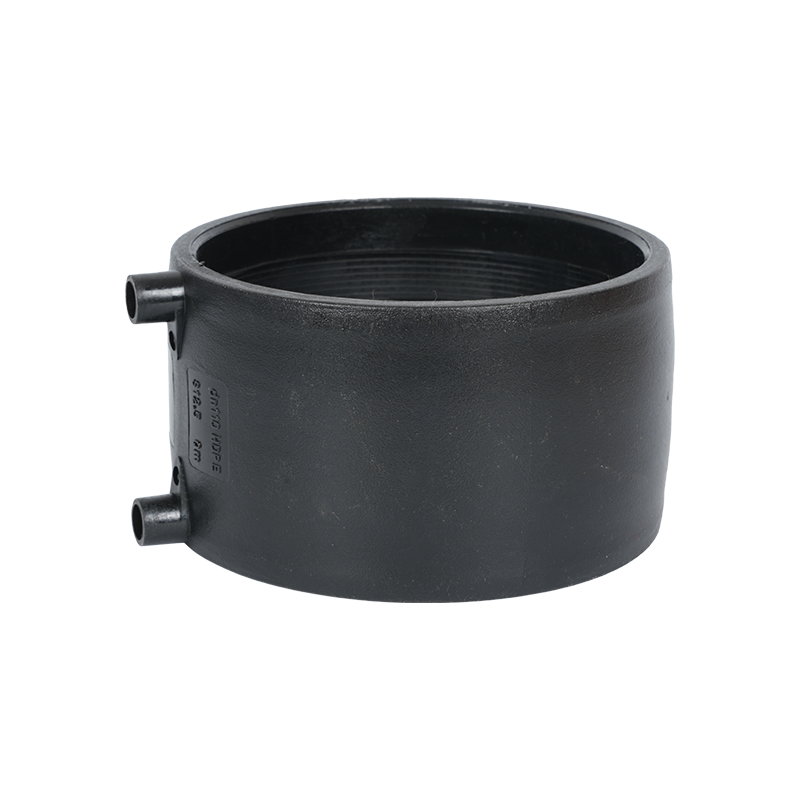
Employs molded couplers, tees, and reducers containing embedded resistance wires. When energized, the wires melt the adjacent pipe and fitting material, creating a homogeneous joint under controlled temperature and pressure. Electrofusion is indispensable for repairing existing lines and installing hdpe pipe fittings in tight excavations where butt fusion equipment cannot be aligned.
Saddle Fusion
A localized variant of electrofusion or hot-plate welding used to attach branch hdpe fitting saddles onto a live main. The saddle base conforms to the host pipe curvature. After surface preparation and fusion, a cutter bores through the main wall to establish flow. This technique avoids system shutdown during network expansion.
Mechanical Flange Adapters
Where polyethylene must interface with metallic valves, pumps, or legacy pipelines, a PE stub end fused to the pipe is compressed against a metal backing flange with an elastomeric gasket. This hybrid joint accommodates the stiffness differential while permitting future disassembly. Working pressure is generally limited by the gasket rating rather than the hdpe pipes and fittings material.
Can you use compression fittings on hdpe pipe?
Compression fittings can be installed on HDPE pipe, but their application is restricted to low-pressure, small-diameter, and generally temporary or non-critical circuits. A compression hdpe fitting relies on an elastomeric seal ring compressed by a threaded gland nut against the pipe outer surface. This mechanical grip does not create a molecular bond and is therefore vulnerable to creep-induced seal relaxation over time.
For nominal diameters up to DN63 and operating pressures not exceeding 0.6 MPa, compression couplings offer a convenient, equipment-free assembly method suitable for irrigation laterals, temporary bypass lines, and indoor drainage transitions. However, the joint integrity depends critically on pipe roundness; ovality must remain within 0.5 mm to prevent asymmetric gasket compression. For buried gas distribution, high-pressure water mains, and permanent industrial process lines, butt fusion or electrofusion remains the only acceptable joining technology. Compression hdpe pipe fittings should never be buried directly without access chambers, as future maintenance or retightening would require excavation.
Do pvc fitttings fit on hdpe?
PVC fittings do not directly fit HDPE pipe in any structurally reliable sense. The two materials are chemically and physically incompatible for solvent cementing or direct interference fit. Polyvinyl chloride is an amorphous polar polymer, whereas high-density polyethylene is a semi-crystalline non-polar polyolefin. Solvent cements formulated for PVC rely on dissolving the substrate surface; these solvents do not attack or bond to HDPE.
Furthermore, the thermal expansion coefficients differ by a factor of approximately three. A joint assembled at 20°C would experience differential shear stress during summer ground warming, inevitably opening a leak path. Attempting to thread or force a PVC fitting onto an HDPE pipe compromises both components and voids any warranty or design liability coverage.
When a transition between PVC and HDPE is unavoidable, the correct practice is to install a dedicated transition fitting. One end of the fitting presents a PVC socket compatible with solvent welding, while the opposite end is a PE tail designed for butt fusion or electrofusion to the polyethylene line. An intermediate metallic flange or threaded union may bridge the two thermoplastic sections. Each side of the transition must be independently pressure-tested before backfilling to confirm that neither the hdpe fitting nor the PVC socket leaks under operating stress.
How to connect hdpe pipe to cast iron fittings?
Connecting polyethylene to existing cast iron or ductile iron infrastructure is a common requirement in water main rehabilitation and sewer system upgrades. Because HDPE and iron possess radically different stiffness, weight, and corrosion potentials, a direct rigid connection would fail within months. Two engineered transition methods resolve this interface.
The first method employs a flange adapter system. A PE stub end is butt-fused to the HDPE pipeline. A loose metallic backing flange slides over the pipe, and a gasket is placed between the PE flange face and the machined cast iron flange. Bolts are tightened in a star pattern to the torque specified by the gasket manufacturer. This arrangement permits future disassembly for valve replacement or line isolation while isolating the brittle iron from bending stresses transmitted by the flexible hdpe pipes and fittings.
The second method utilizes a wide-range mechanical coupling with a stainless steel housing and multi-lip EPDM seal. One end of the coupling grips the HDPE pipe outer diameter, while the opposite end engages the cast iron spigot or bell. These couplings tolerate several degrees of angular misalignment and minor diameter variation, making them ideal for repair scenarios where trench conditions prevent precise alignment. After installation, the exterior bolted housing should be wrapped with petrolatum tape or heat-shrink sleeves to prevent galvanic corrosion of the metal components by surrounding soil electrolytes.
HDPE Fittings Product Range and Dimensional Scope
Our manufacturing program covers the full spectrum of hdpe pipe fittings required to build complete pipeline networks without sourcing secondary components from external vendors. Standard injection-molded and fabricated items are available in PE100 and PE80 grades, with SDR classes from SDR7.4 up to SDR41.
Elbows and Bends
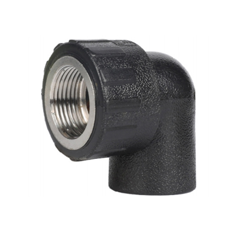
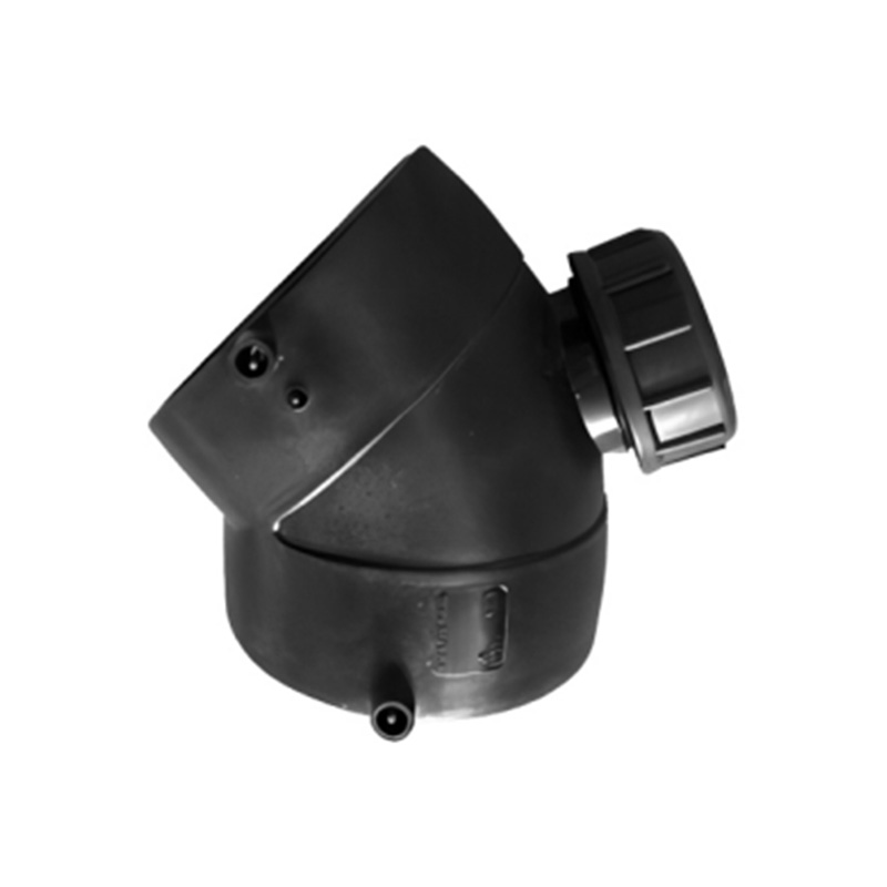
Available in 45-degree and 90-degree configurations, with long-radius sweeps for hydraulic efficiency and short-pattern molded elbows for compact valve stations. Diameters range from 20 mm to 1200 mm.
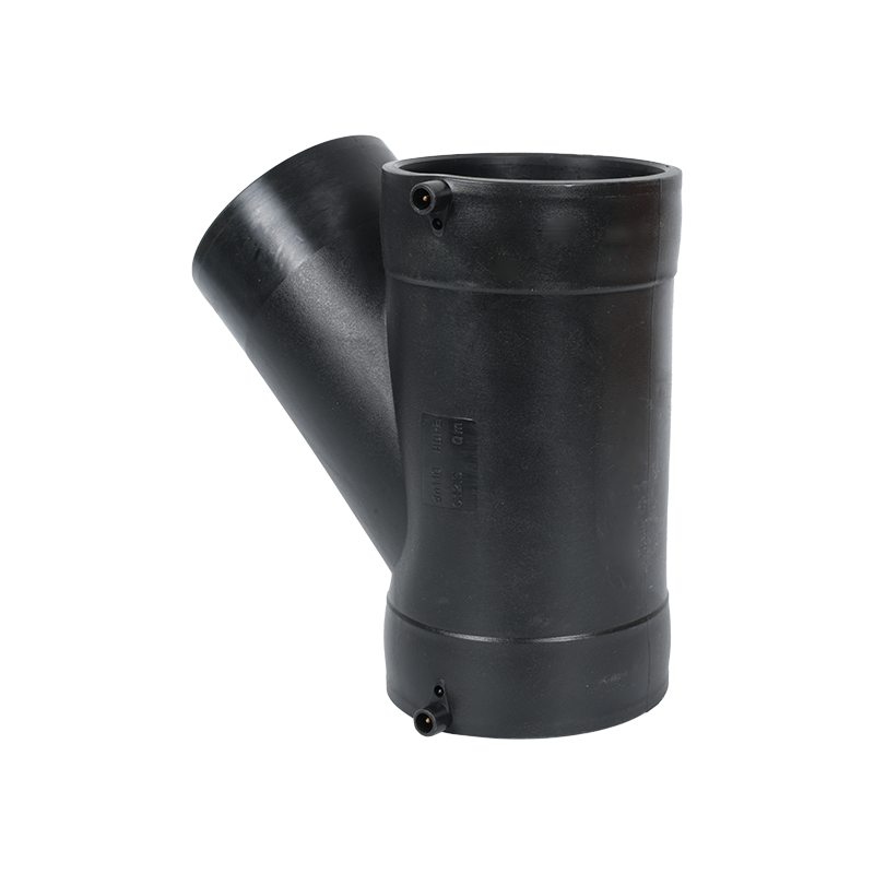
Equal and Reducing Tees
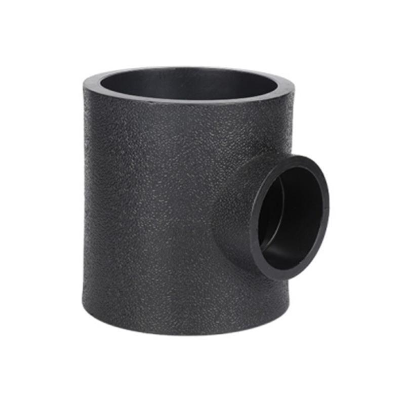
Fabricated segmental tees for large diameters and injection-molded tees for DN630 and below. Reducing variants maintain full pressure rating on all three outlets through engineered wall thickness distribution.
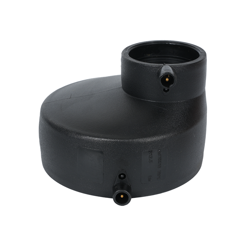
Concentric and Eccentric Reducers
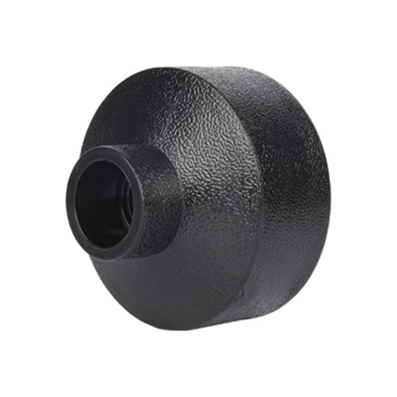
Used to transition between pump flanges and distribution mains. Eccentric designs prevent air pocket formation in horizontal potable water lines. Butt-welded construction ensures axial alignment.
Flange Adapters and Backing Rings
PE stub ends fused to the pipeline, paired with hot-dip galvanized or stainless steel backing rings. Gasket seats are precision-machined to accommodate standard EN 1092-1 and ASME B16.5 drilling patterns.
End Caps and Blind Flanges
Injection-molded end caps for temporary hydrostatic test isolation and permanent line termination. Thick-wall sections at the dome apex resist pressure thrust during pneumatic testing.
Electrofusion and Saddle Couplers
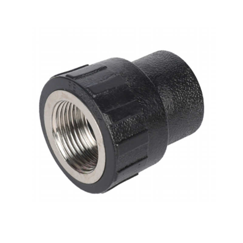
Universal saddle designs for branch take-offs, repair clamps, and tapping tees. Integrated wire coils ensure uniform heat distribution during the fusion cycle, producing consistent weld bead geometry.
| Fitting Category | Size Range (mm) | Pressure Rating (PN) | Manufacturing Method |
| Molded Elbows | 20 – 630 | PN6 – PN25 | Injection Molding |
| Fabricated Tees | 315 – 1200 | PN4 – PN16 | Butt-Welded Segments |
| Reducers | 90 – 1000 | PN6 – PN20 | Fabrication / Molding |
| Flange Adapters | 50 – 1200 | PN6 – PN25 | CNC Machined Stub Ends |
| Electrofusion Couplers | 20 – 630 | PN10 – PN25 | Electrofusion Molding |
| Saddle Fittings | 63 – 630 (Main) | PN10 – PN16 | Injection Molding |
Manufacturing Excellence and Quality Verification
Every batch of hdpe fittings leaving our facility is traceable to the original resin lot number, production shift, and fusion parameter validation record. Raw material certification confirms compliance with ISO 4427 and EN 12201 cell classification requirements for density, melt flow index, and slow crack growth resistance.
Dimensional Verification
CMM inspection protocols check socket internal diameters, fusion zone lengths, and wall thickness at 12 circumferential points. Tolerances are held within ±0.5 percent for molded items and ±1.0 percent for fabricated assemblies.
Hydrostatic Validation
Sample hdpe pipe fittings undergo sustained pressure testing at 1.5 times nominal pressure for 1,000 hours. Additional short-term burst tests confirm that failure always occurs in the pipe wall rather than the fusion zone, validating joint integrity.
Oxidation Induction Time
Differential scanning calorimetry measures the oxidative stability of the compound. A minimum OIT of 20 minutes at 200°C guarantees that the carbon black dispersion and antioxidant package will protect hdpe pipes and fittings throughout the design lifespan.
Environmental Stress Crack Resistance
Notched pipe specimens are subjected to the full-notch creep test at 80°C and 4.0 MPa ring stress. Pass criteria demand survival beyond 500 hours without crack propagation, ensuring that surface imperfections in the field will not initiate brittle fracture.
Specifying the correct hdpe pipe fittings grade, SDR class, and fusion methodology transforms a simple material purchase into a long-term infrastructure investment. Whether your project involves a municipal potable water trunk, a corrosive industrial effluent line, or a gas distribution network requiring zero leakage, the technical parameters and installation disciplines outlined above provide the foundation for decades of reliable service. Our engineering team remains available to review trench details, pressure profiles, and transition requirements to ensure that every hdpe fitting specified is the optimal match for its intended duty.
KEEP IN TOUCH

About Us
Zhejiang Fengfeng Pipe Industry Co., Ltd. uses efficient single screw injection molding machines for high productivity and low energy use.
Products link
Contact
-

+86-19858193396
+86-13735359894 -

+86-0574-63555288
-

-

No. 21, Market Road, Diankou Town, Zhuji City, Shaoxing City, Zhejiang Province, China